Engine tuck and Engine bay shave
#21
 04-12-2010, 02:10 PM


I just did some more blasting today (trying to beat the rain) and I'm designing the linkage to tuck the pressure assist and a mount to tuck the wiper motor but still use it.
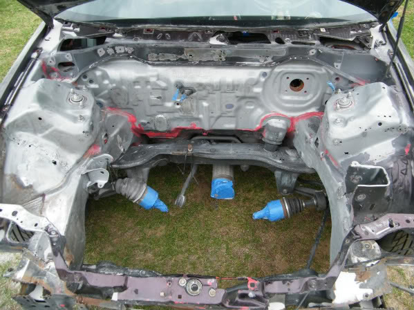
I made some calls and I am going to be able to use someones tig later this week. I am tired of blowing through the firewall with my fluxcore.
I made some calls and I am going to be able to use someones tig later this week. I am tired of blowing through the firewall with my fluxcore.
#22
04-13-2010, 02:52 PM
While I wait to use my friends tig I decided to get some other things done. I am tucking the wiper motor but I am still going to be able to use the wipers.
With the motor, removed the motor and started making a new bracket for the motor. Every bolt was at a different angle which made it fun.
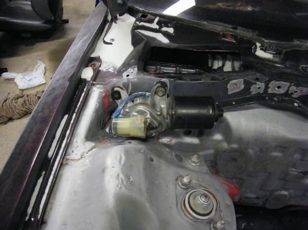
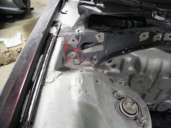
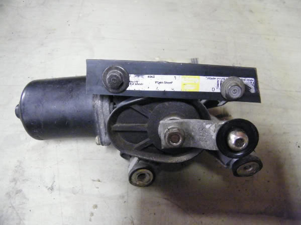
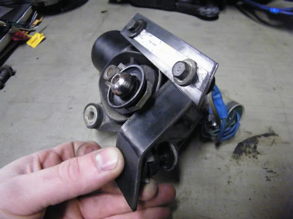
Then I went inside and started cutting out metal for the new motor placement.
Set in the motor to get an idea of clearance.
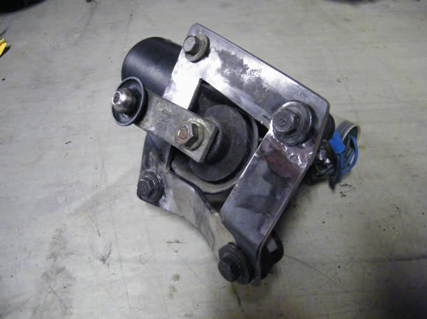
After some more trimming I made legs to attach the motor to the car. I used some temp hardware to mock it up.
Once I weld the original driveshaft hole and mount holes shut, this will be a functional wiper motor tuck.
With the motor, removed the motor and started making a new bracket for the motor. Every bolt was at a different angle which made it fun.
Then I went inside and started cutting out metal for the new motor placement.
Set in the motor to get an idea of clearance.
After some more trimming I made legs to attach the motor to the car. I used some temp hardware to mock it up.
Once I weld the original driveshaft hole and mount holes shut, this will be a functional wiper motor tuck.
Last edited by fabmaster; 04-13-2010 at 11:21 PM.


#25
04-16-2010, 06:37 PM
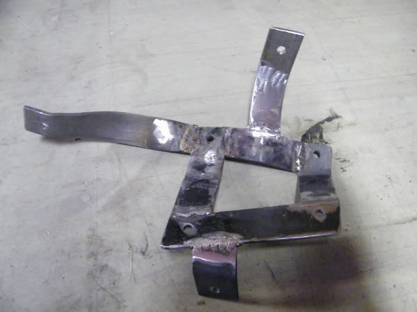
I've been working on the linkage to transfer the forward motion of the brake pedal, to a lateral motion to plunge the pressure assist once it is mounted inside the firewall. I started with cardboard templates and then transfered the idea to sheet stock.
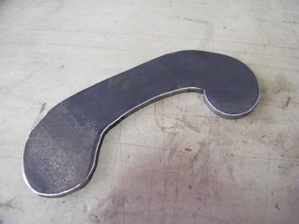
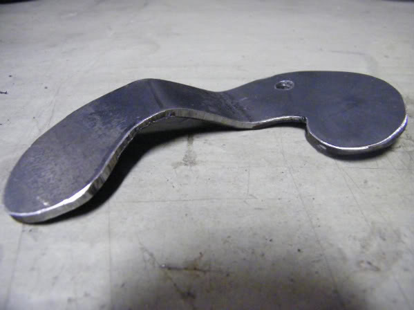
Since this is for the brakes, I don't want to risk a lightweight setup, so I welded on a layer of thicker stock once the bends were right.
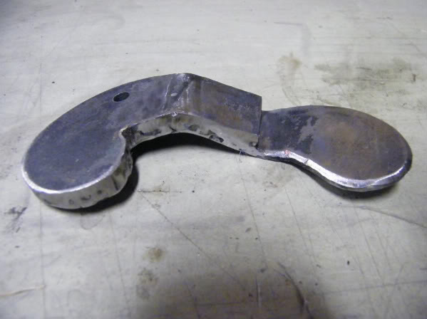
I tested and retested until I finalized the pivot points for the most motion with the least binding.
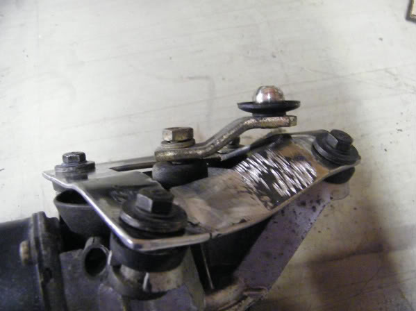
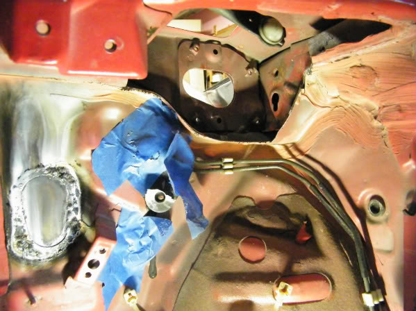
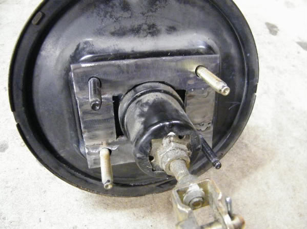
I'm using the stock pin hole through the brake bedal bar for my first linkage point. I had to make a bracket to lock into that hole and then transfer to the plate I just made
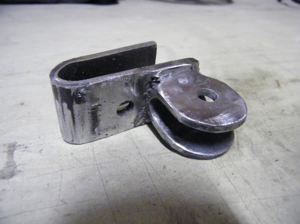
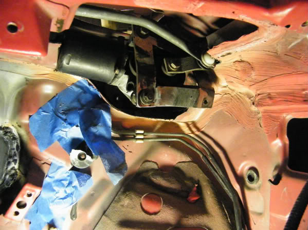
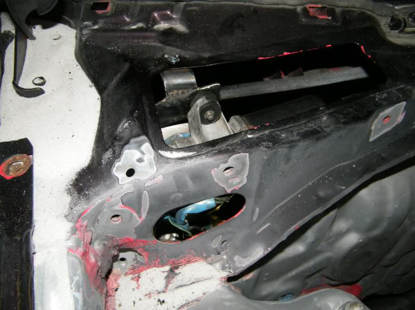
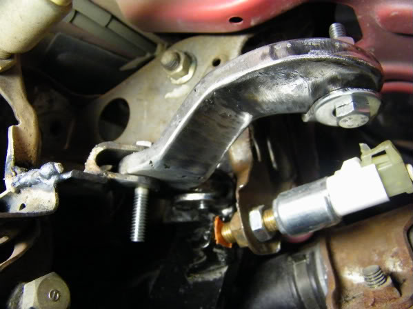
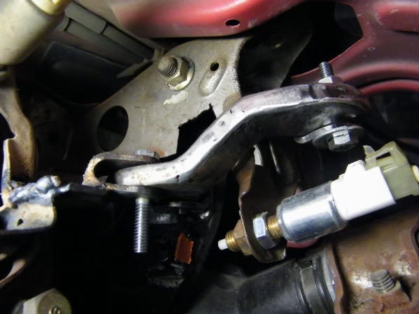
Here you can see the stock hole once the original pressure assist bracket was removed. I mounted my new bracket and then installed the plate. From this I was able to build a mount for the pivot point.

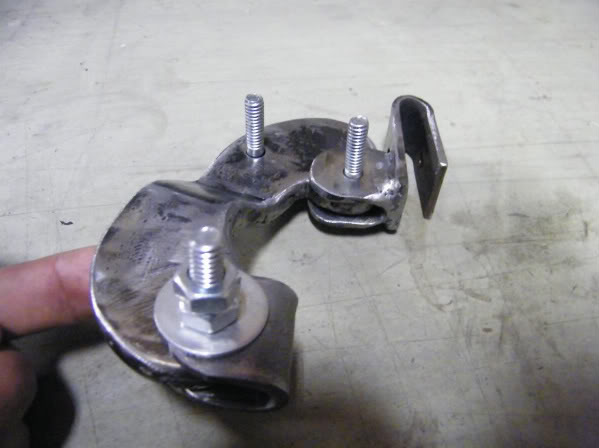
I welded in the bracket for the pivot. You can see that when the brake is pushed, the plate transfers the motion sideways. I still have to mount the pressure assist and then weld up an arm to link the end of the plate to the plunger.
I'll be mounting everything this weekend and then I can post pics that better show what is going on.
Since this is for the brakes, I don't want to risk a lightweight setup, so I welded on a layer of thicker stock once the bends were right.
I tested and retested until I finalized the pivot points for the most motion with the least binding.
I'm using the stock pin hole through the brake bedal bar for my first linkage point. I had to make a bracket to lock into that hole and then transfer to the plate I just made
Here you can see the stock hole once the original pressure assist bracket was removed. I mounted my new bracket and then installed the plate. From this I was able to build a mount for the pivot point.
I welded in the bracket for the pivot. You can see that when the brake is pushed, the plate transfers the motion sideways. I still have to mount the pressure assist and then weld up an arm to link the end of the plate to the plunger.
I'll be mounting everything this weekend and then I can post pics that better show what is going on.
#27
04-17-2010, 07:35 PM
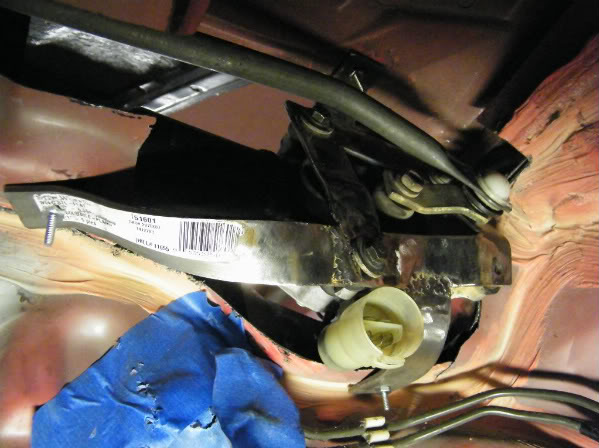
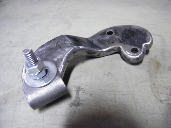
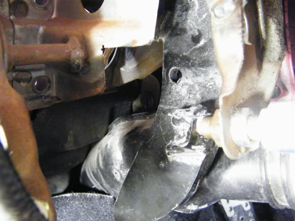
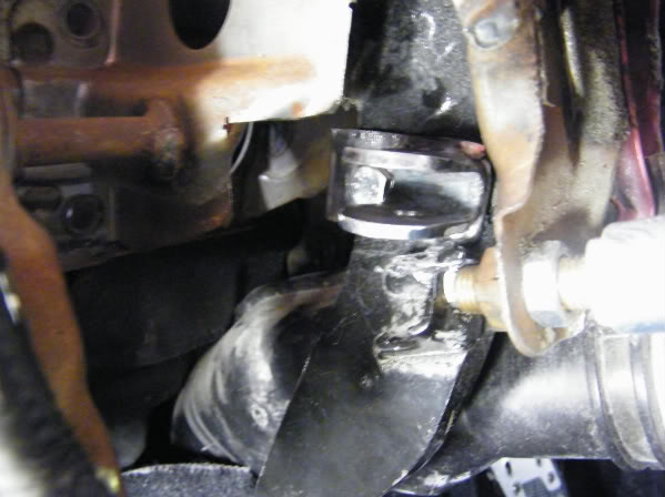
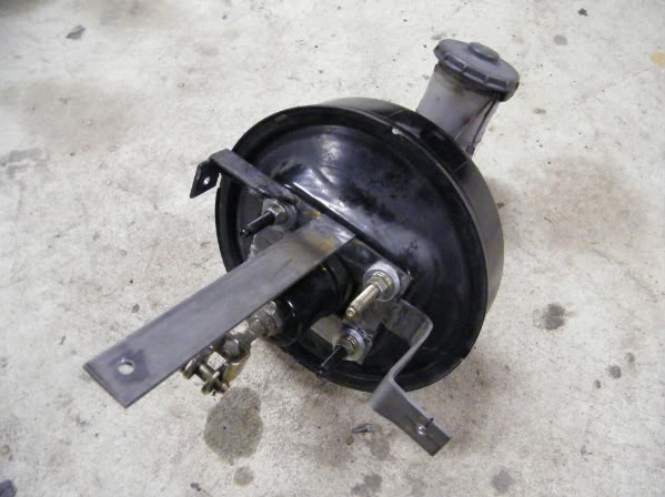
I built a new mount for the pressure assist and got multiple anchor points to make everything solid.
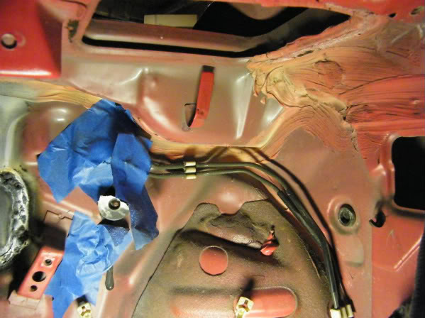
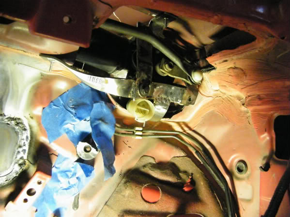
Here you can see why I needed to make the forward motion of the pedal turn 90 degrees to plunge the pressure assist. It is now inside and turned 90 degrees. Don't mind the spider web, I have the previous owner to thank for a hugh cluster-f@%k.
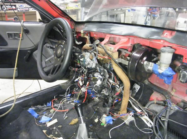
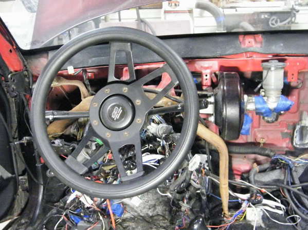
Now when you look through the steering column brace(which was nice and open for my new bracket) you can see that the plate I made lines up with the plunger and all I have to do is make a bar that connects the two.

#28
04-17-2010, 07:40 PM

I'm Spock Dammit!!!!!
Ah that does make sense now haha nice work dang this car is gonna be sick as hell once its done but thats an odd place to put the brake pump but its for a show car not practicality lmao
#29
04-17-2010, 07:50 PM
Glad it's clearer now. It is an odd place, but I will have a center channel speaker above it so if I need to check/fill the fluid, I just have to take out four screws. This is my show car but it is also my DD. I'm just lucky that I can drive my gf's car while I do this overhaul.