


Speed-Glo Electroluminescent gauge wiring query


Thread Starter
|
Junior Member
Joined: Mar 2009
Posts: 13
From: Greater Manchester, England
 Speed-Glo Electroluminescent gauge wiring query
Hello all!
I'm trying to get some clarification on wiring the dimmer switch of my Speed-Glo Electoluminescent Gauges to my fuse box. I've read through the archives, but all I can extract is "wire your live cable to the fuse box" - but I just don't know how, or where. I'm completely new to auto-electronics.
I have a photograph of my dimmer switch at http://www.flickr.com/photos/jza84/3401537342/ (with red live and black ground wires), and another of my 1997 EK fuse box at http://www.flickr.com/photos/jza84/3400733219/. From what I can gather from older threads, I'm meant to wire my red wire into the same power source as my parking lights (something to do with fuse number 32 in my case then). Does that mean taking out fuse 32 and running the red wire through/under it and putting it back? It's that bit I'm confused about and need more detail. Also, where is best to "ground" my black wire? How would I hold them in place? Do I need to worry about Amps and Volts?
Pulling the dash apart isn't a worry, being a father I'm more worried about causing an electrical fire via trail and error here.
Sorry if this has been covered else where; I've Googled but failed to find anything.
I'm trying to get some clarification on wiring the dimmer switch of my Speed-Glo Electoluminescent Gauges to my fuse box. I've read through the archives, but all I can extract is "wire your live cable to the fuse box" - but I just don't know how, or where. I'm completely new to auto-electronics.
I have a photograph of my dimmer switch at http://www.flickr.com/photos/jza84/3401537342/ (with red live and black ground wires), and another of my 1997 EK fuse box at http://www.flickr.com/photos/jza84/3400733219/. From what I can gather from older threads, I'm meant to wire my red wire into the same power source as my parking lights (something to do with fuse number 32 in my case then). Does that mean taking out fuse 32 and running the red wire through/under it and putting it back? It's that bit I'm confused about and need more detail. Also, where is best to "ground" my black wire? How would I hold them in place? Do I need to worry about Amps and Volts?
Pulling the dash apart isn't a worry, being a father I'm more worried about causing an electrical fire via trail and error here.
Sorry if this has been covered else where; I've Googled but failed to find anything.


The really easy/less professional way is to find a fuse, like your fuse 32, pull it, stick the "live wire cable" in, and jam the fuse in to get power.
The SAFER, BETTER way is to do this: Look at this diagram of the fuse box. If you don't have an alarm or anything extra, you'll have some open plugs that aren't for fuses. They're numbered 1,2,3,4.
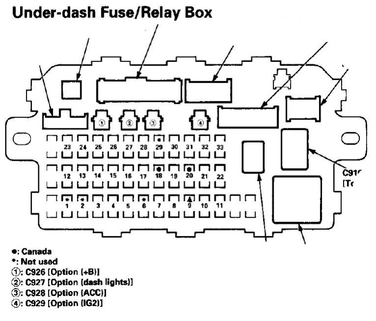
For your purposes, 1 and 2 are in use. I would use 4 because they'll only work when the ignition is in position 2 (IG2). You CAN use 3 for accessory power if you want to use it when the key is out of the ignition, but I don't recommend it because it could drain your battery.
All you need is a female connector to crimp onto that power wire, and then onto the male plug on the fuse box in 4 (or 3).
You can ground the wire under any bolt that is going into the frame or core support. If you remove the lower dash panel under the steering wheel (3 screws) and look at the knee bolster (metal core support) under it, you may find a bolt to ground to.
The SAFER, BETTER way is to do this: Look at this diagram of the fuse box. If you don't have an alarm or anything extra, you'll have some open plugs that aren't for fuses. They're numbered 1,2,3,4.
For your purposes, 1 and 2 are in use. I would use 4 because they'll only work when the ignition is in position 2 (IG2). You CAN use 3 for accessory power if you want to use it when the key is out of the ignition, but I don't recommend it because it could drain your battery.
All you need is a female connector to crimp onto that power wire, and then onto the male plug on the fuse box in 4 (or 3).
You can ground the wire under any bolt that is going into the frame or core support. If you remove the lower dash panel under the steering wheel (3 screws) and look at the knee bolster (metal core support) under it, you may find a bolt to ground to.
Thread Starter
|
Junior Member
Joined: Mar 2009
Posts: 13
From: Greater Manchester, England
Ah ha! OK, that's made much, much more sense thank you.
I think I'll go with your recommendation, i.e. wiring into open port number 4.
Do I need to get hold of a compatible connector then, so that it "plugs" into that port? (I imagine that's the proper way of doing it - if so, does that have a name, so I can eBay it?) Or can I simply "hook" or "tie" the live wire onto the exposed metal and use tape?
My fears of electrical fire have been quelled a little here, so thanks!
I think I'll go with your recommendation, i.e. wiring into open port number 4.
Do I need to get hold of a compatible connector then, so that it "plugs" into that port? (I imagine that's the proper way of doing it - if so, does that have a name, so I can eBay it?) Or can I simply "hook" or "tie" the live wire onto the exposed metal and use tape?
My fears of electrical fire have been quelled a little here, so thanks!
Thread Starter
|
Junior Member
Joined: Mar 2009
Posts: 13
From: Greater Manchester, England
Apparently the connect connectors are variously called "Option Plugs", "Honda Option Plugs" or "Brown Option Plugs", and are only really found in scrap yards... at least according to my Googling. But you mentioned female crimp-on connectors, so I might try get hold of one of those, unless someone knows where to get hold of Option Plugs?
I dunno the plug name, but all you need is a female connector. I forget what they're called, but you can buy them in any store. You probably could get away with hooking or tying, but it's not the safest route. Its best if you do it right the first time and don't have to worry about it later.
What you need is called a "female spade connector." They look like this:

Or if you can salvage a honda connector from a junk yard and splice the wires together, that would work just as well.
What you need is called a "female spade connector." They look like this:
Or if you can salvage a honda connector from a junk yard and splice the wires together, that would work just as well.
Thread Starter
|
Junior Member
Joined: Mar 2009
Posts: 13
From: Greater Manchester, England
Thanks for this. I've got the spade connectors on the way to me.
I'll try to document the process with photographs to leave as a guide for others. I'll make sure I get a snapshot of the finished product too.
I'll try to document the process with photographs to leave as a guide for others. I'll make sure I get a snapshot of the finished product too.
Thread Starter
|
Junior Member
Joined: Mar 2009
Posts: 13
From: Greater Manchester, England

Worked a treat! Struggled with the earthing more than the live wiring; the bolts must've been screwed in via robot and I simply could not undo them, at least with my tools. Managed to earth it against the chassis in the end though.
Thanks for this advice. I'll try do a write up.

Thread
Thread Starter
Forum
Replies
Last Post
